


- Posts: 4
HTF pump
- Javier Rodriguez
- Topic Author
Less
More
24 May 2017 04:21 #5469
by Javier Rodriguez
HTF pump was created by Javier Rodriguez
Hi
In parabolic Trough
What is the difference between "Parasitic power solar field HTF pump" and "Parasitic power TES and Cycle HTF pump"?
What is the difference between Cycle HTF mass flow rate and Field HTF mass "flow rate total"
Thanks so much
In parabolic Trough
What is the difference between "Parasitic power solar field HTF pump" and "Parasitic power TES and Cycle HTF pump"?
What is the difference between Cycle HTF mass flow rate and Field HTF mass "flow rate total"
Thanks so much
Please Log in or Create an account to join the conversation.
- Paul Gilman
Less
More
- Posts: 5707
12 Jun 2017 12:28 #5470
by Paul Gilman
Replied by Paul Gilman on topic HTF pump
Dear Javier,
"Parasitic power solar field HTF pump" is the electrical power consumption of the HTF pumps in the solar field.
"Parasitic power TES and cycle HTF pump" Is the electrical power consumption of the HTF pumps in the TES (storage) system and power cycle.
The diagram in SAM's help system "Physical Trough Model" topic might be helpful for understanding the mass flow rates. The cycle HTF mass flow rate is the flow rate of the HTF as it enters the power cycle heat exchanger, and the field HTF mass flow rate total is the mass flow rate of the HTF through the receivers and piping in the solar field.
Best regards,
Paul.
Please Log in or Create an account to join the conversation.
- Louw
Less
More
- Posts: 15
17 Sep 2020 11:42 #8752
by Louw
Replied by Louw on topic HTF pump
Dear Paul
I am modeling a physical parabolic trough plant with indirect storage (HTF = Therminol VP1, heat storage fluid (HSF) = Hitec solar salt).
Can you please help me clarify the following output parameters in this regard:
- "TES charge mass flow rate (kg/s)" and "TES discharge mass flow rate (kg/s)": does this refer to the mass flow rate of the HTF or HSF (therefore, thermal oil vs molten salt) for an indirect TES system?
- "Parasitic power TES and cycle HTF pump (MWe)": I understand the cycle HTF parasitic is the pumping power required to pass the HTF (thermal oil) through the power cycle. But does the "parasitic power TES" refer to the power required to pump the HTF through the solar field-side of the TES heat exchanger? Or does it refer to the pumping power required to pump the HSF (molten salt in my case) from cold to hot tank and vice versa?
For my application, I am interested in the charge/discharge mass flow rates of the molten salt on the storage side of the said heat exchanger, as well as the associated pumping power. I just want to clarify whether SAM does report it as output variables for an indirect system, or whether I should calculate them externally.
I will appreciate your advice.
Kind regards
Louw
Please Log in or Create an account to join the conversation.
- Paul Gilman
Less
More
- Posts: 5707
17 Sep 2020 13:06 #8753
by Paul Gilman
Replied by Paul Gilman on topic HTF pump
Hi Louw,
In SAM, when the solar field heat transfer fluid (HTF) is different from the thermal energy storage (TES), the TES is modeled as indirect storage, which is defined has having a storage medium that is different from the field HTF. The "HTF" may be an oil or a salt.
If you are modeling a system with molten salt as the storage medium, then the TES HTF mass flow rate refers to the molten salt.
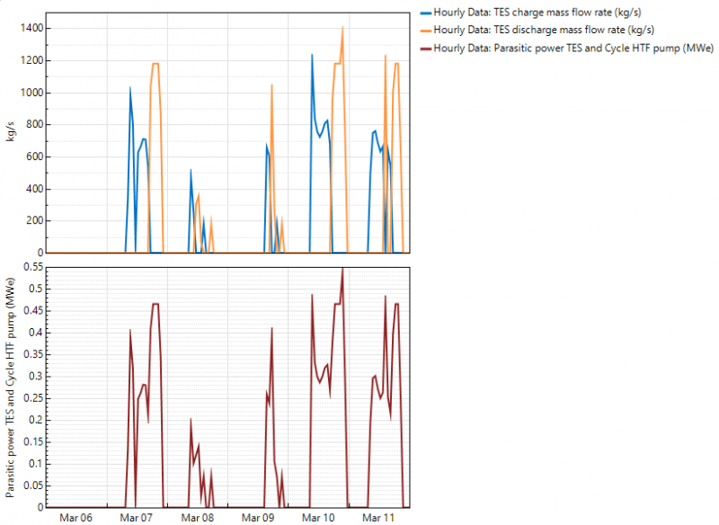
The "Parasitic power TES and Cycle HTF pump" is the sum of pumping power required by the TES and cycle, determined by the "Pumping power for HTF through storage (kJ/kg) input on the Thermal Storage page and "Pumping power for HTF through power block (kW/kg/s)" on the Power Cycle page.
I created the following graph by setting the cycle pumping power to zero to show how the TES pumping power relates to the TES mass flow rates:
Best regards,
Paul.
In SAM, when the solar field heat transfer fluid (HTF) is different from the thermal energy storage (TES), the TES is modeled as indirect storage, which is defined has having a storage medium that is different from the field HTF. The "HTF" may be an oil or a salt.
If you are modeling a system with molten salt as the storage medium, then the TES HTF mass flow rate refers to the molten salt.
The "Parasitic power TES and Cycle HTF pump" is the sum of pumping power required by the TES and cycle, determined by the "Pumping power for HTF through storage (kJ/kg) input on the Thermal Storage page and "Pumping power for HTF through power block (kW/kg/s)" on the Power Cycle page.
I created the following graph by setting the cycle pumping power to zero to show how the TES pumping power relates to the TES mass flow rates:
Best regards,
Paul.
Attachments:
Please Log in or Create an account to join the conversation.
- Louw
Less
More
- Posts: 15
17 Sep 2020 13:59 #8756
by Louw
Replied by Louw on topic HTF pump
Hi Paul
Thank you for the explanation. I agree, I have Hitec solar salt listed as "Storage HTF fluid" and Therminol VP1 listed as "Field HTF fluid". Therefore, indirect storage is applicable.
So as you say, the SAM output TES charge/discharge mass flow rates then refer to the molten salt and not the oil.
As a sanity check however, I performed the following mass balance on the hot side (HTF side) of the TES heat exchanger during a TES charge:
TES charge mass flow rate (sanity check) = Field total mass flow delivered - PC HTF mass flow rate
So the variable on the left of the above equation should represent the mass flow rate of oil in the TES heat exchanger during a TES charge, since the right side of the equation is also for thermal oil.
But when I plot this check-variable against the SAM output "TES charge mass flow rate", I find that they match almost exactly. Slight mismatches could be due to SAM's mass flow balance error?
Please see attached the excel sheet with a graph and sample data. The SAM variable is in the left yellow column, and my check is in the right yellow column.
How can this match be possible, if the SAM output "TES charge mass flow rate" is said to be for molten salt (with a higher density than the oil), and my sanity check was based on thermal oil? I believe the two different fluids should have different mass flow rates (during a charge cycle, for instance).
I hope my explanation and uncertainty is clear.
Thank you for your help.
Best regards
Louw
Attachments:
Please Log in or Create an account to join the conversation.
- Louw
Less
More
- Posts: 15
19 Sep 2020 10:56 #8760
by Louw
Replied by Louw on topic HTF pump
Hi Paul
An additional query of mine is the following:
If we consider an energy balance on the storage side of the TES heat exchanger
Q = (dm/dt)*c_p*dT/1000 => c_p = 1000*Q/[(dm/dt)*dT] (kJ/kgK)
with
Q = either "TES charge thermal power MWt" or "TES discharge thermal power MWt"
dm/dt = either "TES charge mass flow rate" or "TES discharge mass flow rate"
dT = "TES hot temperature" - "TES cold temperature" (an estimate of the HSF temperature change during charge or discharge)
then one can calculate the approximate c_p of Hitec solar salt as HSF (please see attached an excel spreadsheet).
But this calculated value seems to be well above range of typical c_p's listed for Hitec solar salt in literature (see for example sterg.sun.ac.za/wp-content/uploads/2011/08/HTF_TESmed_Review_2013_05_311.pdf on page 60) and more in range of c_p for Therminol VP-1 (see page 59).
Even though I specified Therminol VP-1 as the HTF and Hitec solar salt as HSF, it seems that the said TES output parameters in SAM are reported for the HTF (Therminol) and not the HSF (molten salt) for an indirect TES system?
I look forward to hearing from you.
Kind regards
Louw
Attachments:
Please Log in or Create an account to join the conversation.
Moderators: Paul Gilman