


- Posts: 5
CSP IPH Model: HTF Fluid Outlet Temperature
- Marco Colombi
- Topic Author
Less
More
24 Jan 2024 01:08 #12852
by Marco Colombi
CSP IPH Model: HTF Fluid Outlet Temperature was created by Marco Colombi
Hi,
I have a question about the control strategy that is adopted in SAM regarding the HTF outlet temperature.
I know that in Design Conditions this temperature is fixed and the flowrate of HTF is computed according to the design DNI, the solar multiple selected and so on.
I know also that when DNI is lower than the design one the system should decrease the HTF flowrate in order to maintain this outlet temperature constant, till the point in which the flowrate would be lower than the minimum one allowed and so a reduction in HTF outlet temperature is accepted.
However, in my simulations this behaviour is not exactly like that on the first hours of operation. What I mean is that in the first hours of radiation during the day, after the system has been heated up enough, the HTF Is delivered for one hour at a temperature lower than the set point with a flowrate higher than the minimum one. But how is this possible? Should the algorithm always impose the design outlet temperature when possible?
I noticed this behaviour practically in each Parabolic Trough model available. Is there any way to fix It? (Also maybe by acting on the open source code...but where?)
Because for IPH applications it's very important to have the right temperature most of the time.
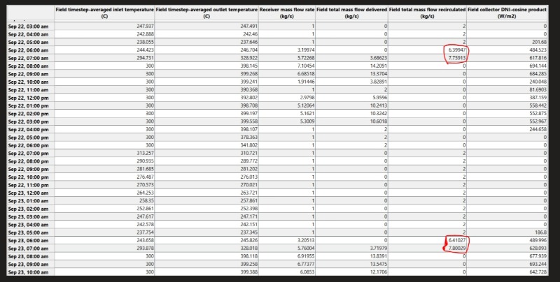
In attachment an example of what I mean. As can be seen there is a moment After start up in which a flowrate higher than the minimum is delivered and It Is at a temperature fare lower than the requested one.
I have a question about the control strategy that is adopted in SAM regarding the HTF outlet temperature.
I know that in Design Conditions this temperature is fixed and the flowrate of HTF is computed according to the design DNI, the solar multiple selected and so on.
I know also that when DNI is lower than the design one the system should decrease the HTF flowrate in order to maintain this outlet temperature constant, till the point in which the flowrate would be lower than the minimum one allowed and so a reduction in HTF outlet temperature is accepted.
However, in my simulations this behaviour is not exactly like that on the first hours of operation. What I mean is that in the first hours of radiation during the day, after the system has been heated up enough, the HTF Is delivered for one hour at a temperature lower than the set point with a flowrate higher than the minimum one. But how is this possible? Should the algorithm always impose the design outlet temperature when possible?
I noticed this behaviour practically in each Parabolic Trough model available. Is there any way to fix It? (Also maybe by acting on the open source code...but where?)
Because for IPH applications it's very important to have the right temperature most of the time.
In attachment an example of what I mean. As can be seen there is a moment After start up in which a flowrate higher than the minimum is delivered and It Is at a temperature fare lower than the requested one.
Please Log in or Create an account to join the conversation.
- Ty Neises
Less
More
- Posts: 20
23 Feb 2024 11:38 - 23 Feb 2024 12:02 #12937
by Ty Neises
Replied by Ty Neises on topic CSP IPH Model: HTF Fluid Outlet Temperature
Hi Marco,
At night, the trough recirculates the HTF at the minimum flow rate from its outlet to its inlet rather than stop mass flow rate. This operation allows the components in the entire fluid loop to slowly change temperature. When the trough is in recirculating mode, we divide the hourly timestep into shorter “subtimesteps” that help the equations balance energy.
In the morning, the trough continues recirculating fluid until the outlet temperature reaches a threshold temperature that we currently fix internally in the code based on a weighted average equal to the 33% the design point hot temperature and 67% the design point cold temperature. This recirculation occurs at a mass flow rate close to the approximated “steady state” mass flow rate at the timestep DNI rather than the minimum mass flow.
Because we solve at subtimesteps, the model often reaches this temperature threshold partway through a timestep. Then, the trough switches operation to deliver HTF to the process or TES, and likewise the inlet HTF comes from the process or TES outlet. After this switchover, the outlet temperature in this case must climb from the threshold temperature to the design temperature.
The reported hourly “Receiver mass flow rate” and “Field timestep-averaged outlet temperature” are averaged over the entire timestep.We currently are exploring different values for the threshold temperature and whether to make that value accessible as a user input in the UI.
Hourly outputs make it challenging to represent an output stream when two different operating modes occur during the hour, but we will think about ways to clarify the results.
Last edit: 23 Feb 2024 12:02 by Paul Gilman.
Please Log in or Create an account to join the conversation.
- Marco Colombi
- Topic Author
Less
More
- Posts: 5
25 Feb 2024 08:10 #12945
by Marco Colombi
Replied by Marco Colombi on topic CSP IPH Model: HTF Fluid Outlet Temperature
Hi Ty,
thank you for your answer.
1) Just to check if I understood correctly, referring to the previous attachment, during Sept 22 7.00 am in which I have both a delivered and a recirculated HTF flowrate and so like you said there's the switch of operation, what happens in reality is that in the first part of the hour the system is only recirculating HTF flowrate to reach an outlet temperature equal to the threshold one (which in this case should be 400*0.33+300*0.67 = 333°C) while in the second part the operation is switched and so I start delivering HTF flowrate to the process at a temperature that goes from the threshold one to the one that I can achieve at the end of the hour, right?
2) My question now is how to consider this from an energy perspective, being interested only in the power and temperature available for the heat sink. What I would need are the average power and the average outlet temperature of the HTF in that hour. How can I obtain them?
I know that the variable "Field Thermal Power Leaving HTF" gives the available power of the field flowrate, which can be divided in recirculated and delivered in this particular hour, right? If I'm only interested in the delivered power, I suppose I can multiply the "Field Thermal Power Leaving HTF" times the ratio between the HTF delivered flowrate and the sum of the delivered and recirculated flowrate or maybe computing the product between delivered flowrate, averaged Cp and averaged DeltaT in the hour.But is this power the averaged power delivered to heat sink by the system in that hour? And if so, how can I obtain a rough estimate of the averaged temperature at which is provided? Since I imagine that the averaged outlet temperature given in SAM is an average considering both operations (recirculating till T threshold and starting of the delivery) and so it wouldn't be so representative of the averaged outlet T of the delivery part only.Hope my questions are clear and thanks in advance for your precious answers.Kind regards,
Marco
Please Log in or Create an account to join the conversation.
- Ty Neises
Less
More
- Posts: 20
07 Mar 2024 08:13 - 07 Mar 2024 15:47 #12963
by Ty Neises
Replied by Ty Neises on topic CSP IPH Model: HTF Fluid Outlet Temperature
Hi Marco,
Your description in 1) is correct.Please note that SAM includes hourly outputs representing the heat sink: “Heat sink HTF inlet temp (C)”, “Heat sink HTF mass flow (kg/s)”, etc. These outputs represent the hourly average value. The challenge is that when an hourly timestep consists of (for example) 40% recirculation and 60% delivering heat to the heat sink.
In this case (without TES to buffer the field from the heat sink), the heat sink inlet temperature is calculated as 0.4*(Design heat sink inlet temperature) + 0.6*(Calculated heat sink inlet temperature) and the heat sink mass flow rate is calculated as 0.4*(0.0) + 0.6*(calculated mass flow rate).
The mass flow rate is a good representation of the average hourly value, but of course it underestimates the actual mass flow the heat sink sees when it is operating for the 60% of the timestep.
The temperature output is more uncertain in these cases because its average includes a design-point value when the heat sink is not operating. We’ll think about ways that we can improve outputs for these “multi-operation” timesteps.
Last edit: 07 Mar 2024 15:47 by Paul Gilman.
Please Log in or Create an account to join the conversation.
Moderators: Paul Gilman