


- Posts: 3
High Power Inverter Clipping Issue
- Brian
- Topic Author
Less
More
22 Jul 2021 12:59 #9859
by Brian
High Power Inverter Clipping Issue was created by Brian
When using some higher power (2-3MW) inverters (e.g. SMA SC 2750-EV-US and Power Electronics FS2250CU15O3) with a DC/AC inverter loading ratio of ~1.50, the clipping losses do not appear to be reflected in the time series data for "inverter clipping loss AC power limit (kW)" or the system loss diagram (0% inverter power clipping). It does appear that the result of the clipping is reflected in the time series data for the "system power generated (kW)", but also oddly appears to show up in the time series data for the "inverter DC input power (kW)", which I would have expected to more closely match the profile of the irradiation curve vs. the AC output power curve.
If I use the Sungrow SC2500U inverter with a similar DC/AC inverter loading ratio, the power clipping losses are seen in both the time series data and the system loss diagram (2.99% inverter power clipping)
The attached file includes a battery, but this same issue occurred on a PV only design as well.
Your help in trouble shooting and educating is appreciated.
Attachments:
Please Log in or Create an account to join the conversation.
- Paul Gilman
Less
More
- Posts: 5707
22 Jul 2021 16:13 #9864
by Paul Gilman
Replied by Paul Gilman on topic High Power Inverter Clipping Issue
Hi Brian,
There are a few differences between the two system designs that affect the inverter AC power limiting: The array string lengths and number of strings are different, so the array operates at a different power levels for the two systems, and the inverters have different properties like self consumption and maximum voltage.
The DC array power for "inverter with clipping issue" system never causes the inverter power to exceed its rated AC value, so there is never any power limiting for that case. I changed the number of modules per string and strings in parallel (on the System Design page) for that case to match the values for the "inverter with out clipping issue" case, which resulted in more comparable power limiting losses.
Best regards,
Paul.
Please Log in or Create an account to join the conversation.
- Brian
- Topic Author
Less
More
- Posts: 3
24 Aug 2021 09:52 #9985
by Brian
Replied by Brian on topic High Power Inverter Clipping Issue
Thank you for the response Paul,
I have tried to put together another file to better illustrate the issue I am having.
After further tinkering the issue I am observing appears to be related to the "inverter thermal derate DC power loss (kW)", which does not show up in the standard sankey loss diagram. This output is not shown in the previous time series screen captures so I attached a new .sam file (system-3,4,5,6-v01.sam) and screen captures where I was playing around and made the observation. Side note it would be nice if SAM cached/saved the simulation results and data trends when you close the application, so you do not need to re-run the simulation and re-trend everything every time you open the file.
In "system-3,4,5,6-v01.sam" I use the same module but a different inverter in each system and change the maximum DC array power of the system to result in an ILR of ~1.5 and allow the auto sizing function to adjust the module strings in parallel accordingly.
You will see in the screen captures of the time series data for systems 3 and 5 that the system clips as expected and as described in the power clipping information in the help file, with no spikes for the "inverter thermal derate DC power loss (kW)" data, and spikes in the "inverter clipping loss AC power limit (kW)" data.
System 4 however clips in a way that in my opinion does not fit the help file description for MPPT or power clipping, and shows significant spikes for "inverter thermal derate DC power loss (kW)", and no spike in the "inverter clipping loss AC power limit (kW)" data. I reviewed the inverter temperature derate curves, and they appear to be identical for all inverters, and all systems share the same location (weather data) and therefore ambient temperature and the same modules.
The impact of the "inverter thermal derate DC power loss (kW)" can been seen even at lower ILR (~1.0).
Can you help me understand what is going on, this appears to be a common issue across the high power inverters in the database? Is there is an inverter specification/attribute that would indicate that an inverter is more susceptible to this issue compared to another, as the inverter temperature derate curves do not appear to indicate a difference?
Please Log in or Create an account to join the conversation.
- Brian
- Topic Author
Less
More
- Posts: 3
24 Aug 2021 13:08 #9987
by Brian
Replied by Brian on topic High Power Inverter Clipping Issue
After some additional investigation the issue appears to impact all inverters with a "Vdcmax" and "Mppt_high" of 1200V, I randomly selected around 10 of them and they all exhibited this issue.
Inverters above 1200V (eg. SMA SC2500-EV-US @1425V and SunGrow SC2500U/GE RIU2500 @1500V) and bellow 1100V (eg. SMA SC2200-US @950V and Power Electronics FS1980CU @800V) power clip as expected.
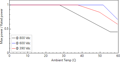
I thought that it might have been related to exceeding the 800V curve in the default "inverter temperature derate curves", but then I would have also expected inverters with maximum voltages of 1425V, 1500V...etc to have been similarly affected.
Inverters above 1200V (eg. SMA SC2500-EV-US @1425V and SunGrow SC2500U/GE RIU2500 @1500V) and bellow 1100V (eg. SMA SC2200-US @950V and Power Electronics FS1980CU @800V) power clip as expected.
I thought that it might have been related to exceeding the 800V curve in the default "inverter temperature derate curves", but then I would have also expected inverters with maximum voltages of 1425V, 1500V...etc to have been similarly affected.
Please Log in or Create an account to join the conversation.
- Paul Gilman
Less
More
- Posts: 5707
25 Aug 2021 15:00 #9997
by Paul Gilman
Replied by Paul Gilman on topic High Power Inverter Clipping Issue
Hi Brian,
There is an interplay between the effect of inverter power losses due to the inverter temperature derate curves, the inverter's maximum voltage rating, and the number of modules per string that is causing these results. When you use the auto-sizing option on the System Design page, SAM sets the number of modules per string based on the inverter maximum voltage ratings, so the different cases you are comparing have different numbers of modules per string.
If you use the same temperature derate curve for the different inverters, the inverters with higher maximum voltage ratings may experience more power losses due to temperature derating if they happen to operate at higher voltage levels. The operating voltage is determined in part by the number of modules per string: Systems with fewer modules per string will operate at lower voltages and experience less temperature derating.
To isolate the effect of inverter maximum voltage rating on temperature derating, you could compare systems with the same number modules per string and inverters with different maximum voltage ratings.
Best regards,
Paul.
Please Log in or Create an account to join the conversation.
- Paul Gilman
Less
More
- Posts: 5707
01 Sep 2021 16:35 - 01 Sep 2021 16:37 #10026
by Paul Gilman
Replied by Paul Gilman on topic High Power Inverter Clipping Issue
Hi Brian,
Here are some more thoughts on this.
The following table shows inputs and results for five systems in the attached .sam file. I started with the file you attached above, but removed System 6 because it was the same as System 4 and added a System 7 with a 1500 V inverter, and a System 7 with the same inverter but modified temperature derate curves.
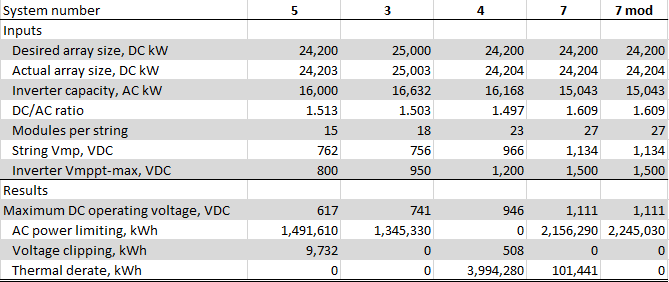
The inverters for Systems 5 and 3 have lower maximum MPPT voltage ratings than the others, so SAM's array autosizing on the System Design page chose shorter string lengths (15 and 18 modules, respectively). These shorter string lengths result in lower operating voltages. On the Statistics tab of the Results page, you can see that maximum ambient temperature for this weather file is 34 degrees Celsius, and the maximum operating voltage for these systems is below 800 VDC. Given the default inverter thermal derate curves, these inverters experience no inverter thermal derate losses.
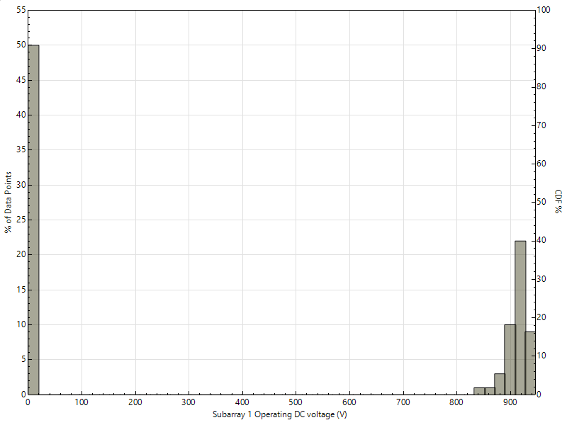
System 4 uses an inverter with 1200 VDC maximum MPPT voltage, so SAM chose a string length of 23 modules, which results in a higher maximum operating voltage of 946 VDC. On the Results page PDF / CDF tab, I created a histogram that shows that the array often operates at voltages above 800 VDC, so it makes sense that it would result in more losses due to the temperature derate curves. These power losses reduce the inverter power so that it does not exceed its nameplate rated power, so the system experiences no power limiting losses.
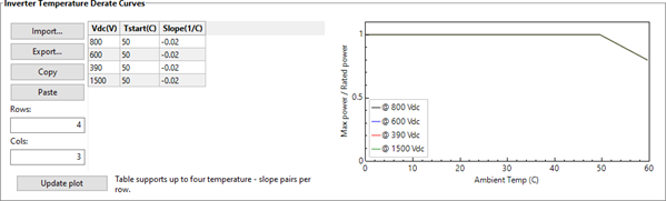
System 7 has the highest DC/AC ratio and inverter nominal voltage, so we would expect it to have the highest power limiting losses and thermal losses. Its maximum operating voltage is 1,111 VDC, but we see thermal derate losses of only 101,441 kWh/yr. Because it is hard to visualize how the inverter thermal derate curves extrapolate from 800 V to 1500 V, I decided to see if the inverter datasheet has any information about response to temperature. The datasheet has a category called "Operating ambient temperature range" of "-30 to 60 degrees C (> 50 degrees C derating)". To model that, I created the system-7 mod case, which is a copy of the system-7 case with a thermal derate curve that matches that description:
I hope that helps. Let us know if you have other questions.
Best regards,
Paul.
Here are some more thoughts on this.
The following table shows inputs and results for five systems in the attached .sam file. I started with the file you attached above, but removed System 6 because it was the same as System 4 and added a System 7 with a 1500 V inverter, and a System 7 with the same inverter but modified temperature derate curves.
The inverters for Systems 5 and 3 have lower maximum MPPT voltage ratings than the others, so SAM's array autosizing on the System Design page chose shorter string lengths (15 and 18 modules, respectively). These shorter string lengths result in lower operating voltages. On the Statistics tab of the Results page, you can see that maximum ambient temperature for this weather file is 34 degrees Celsius, and the maximum operating voltage for these systems is below 800 VDC. Given the default inverter thermal derate curves, these inverters experience no inverter thermal derate losses.
System 4 uses an inverter with 1200 VDC maximum MPPT voltage, so SAM chose a string length of 23 modules, which results in a higher maximum operating voltage of 946 VDC. On the Results page PDF / CDF tab, I created a histogram that shows that the array often operates at voltages above 800 VDC, so it makes sense that it would result in more losses due to the temperature derate curves. These power losses reduce the inverter power so that it does not exceed its nameplate rated power, so the system experiences no power limiting losses.
System 7 has the highest DC/AC ratio and inverter nominal voltage, so we would expect it to have the highest power limiting losses and thermal losses. Its maximum operating voltage is 1,111 VDC, but we see thermal derate losses of only 101,441 kWh/yr. Because it is hard to visualize how the inverter thermal derate curves extrapolate from 800 V to 1500 V, I decided to see if the inverter datasheet has any information about response to temperature. The datasheet has a category called "Operating ambient temperature range" of "-30 to 60 degrees C (> 50 degrees C derating)". To model that, I created the system-7 mod case, which is a copy of the system-7 case with a thermal derate curve that matches that description:
I hope that helps. Let us know if you have other questions.
Best regards,
Paul.
Attachments:
Last edit: 01 Sep 2021 16:37 by Paul Gilman.
Please Log in or Create an account to join the conversation.
Moderators: Paul Gilman